
Wave Spring Worked Example
This page will work through a real life example to show how to apply the design and engineering equations we discussed in our introduction page.
Useful Equations
We begin from first principles:
And for our purposes here, Load is no different to Force.
The equations used for the calculations of Load, Deflection and Stress are derived from those for a simple beam and have the application of some corrective factors based on empirical measurements and experience.
These equations for loads & stresses, are not precise solutions, but they do provide very useful engineering estimates. As a measure of usefulness, they are more accurate and useful than any of the forecasting models Economists use to explain Recessions, but not nearly as accurate as Cosmologists employ to calculate the Hubble Constant.
Some skepticism should be expected if Forces are provided in Newtons with decimal places.
We can now derive various useful metrics, such as:
- Required Material Thickness - t, to support a Load:
- Deflection - s, expected from a Load:
- Induced stress - σ, created by a Load:
- Deflection - s, expected at stress threshold:
What should you use and when?
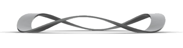
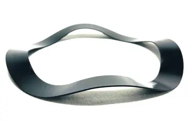
A Simple Worked Design Example
Our Task is to select and verify a wave washer which is needed to fit into an 80mm (3.15”) bore and over a 60mm (2.362”) shaft to support a load of between 500 and 550 Newtons (i.e. 112lbs to 124lbs). The Wave Washer Spring must accommodate at least a 1.8 mm (0.071”) deflection. Furthermore the application requires a steady load. The washer will operate in a benign environment where the ambient temperature will never exceed 30°C.
So, here we have a static application. Let us assume a standard single wave washer spring will do the job to start off with. Go to the menu, Our Products → Wave Springs → Single Turn Wave Springs Sizes and see what there is that might cater for our needs.
You should find a 3 Wave Spring of dimension ID: 61.5mm x OD: 79.5mm x t:0.4mm and the Nominal Load stated as 30N at Working Height / HLoad of 3.0mm on Free Height of 6.5mm. The diameter dimensions look OK, deflection is well over the minimum of 1.8mm, but the Design Load is way too low, can we make an easy change to get what we require? It looks like we will have to add a wave or two or change the material thickness.
Start by checking the material thickness t, if we changed it from 0.4mm to 0.6mm or 0.8mm, what would that do for us?
Using, the following equation, see if we get a reasonable material thickness, before considering adding waves:
We Substitute into the equation above, where:
- N = 3, because we have 3 waves
- k = 3.88 because we have N = 3
- P = 525N, mid way between the required Load range of 500 to 550 Newtons
- D = average of 79.5 and 61.5 = 70.5mm
- b = 9.0mm
- s = 2.0mm because we require at least 1.8mm of Working Travel
Giving us:
and you should get:
We round to a practical strip thickness of t = 1.2 mm. At that thickness the theoretical spring rate is about 248 N/mm, so at the design deflection s = 2.0 mm the theory load is about 496 N (stress about 706 MPa). That is a little below the mid-target of 525 N, but well inside the usual ±15% theory-versus-test band quoted on the intro page, and still inside the 500 to 550 N requirement once manufacturing and test variation are allowed for. (Solving exactly for 525 N at 2.0 mm would give t ≈ 1.22 mm.)
Deflection uses the standard convention s = L0 − H. With free height L0 = 6.5 mm and design travel s = 2.0 mm, the working height is HL = 4.5 mm. The thicker strip still fits the original free-height envelope.
Checking the Stress
We better check that the stresses we induced do not lead to plastic deformation. The operating stress of a single turn wave spring should never exceed the minimum tensile strength of the base material from which it has been formed. Now with Wave Springs, unlike with Conical Disc Springs, we cannot create favourable Residual stresses within this profile, so we set our Maximum Stress at 75-80% of the base material's Tensile Strength. We are using Quench and Double Tempered Spring Steel, which at a Rockwell C hardness of 46-48, has a Tensile Strength of 1650 MPa, giving us σmax of 1240 MPa.
So, at this threshold of stress, what deflection / compression would result?
Substitute into the equation above, where:
- N = 3, because we have 3 waves
- k = 3.88 because we have N = 3 (wave factor)
- D = average of 79.5 and 61.5 = 70.5 mm
- σ = 1240 MPa
- Di = 61.5 mm and De = 79.5 mm
- t = 1.2 mm from our calculation above
Note that radial width b cancels when rate and stress are combined, so it does not appear in this formula. Evaluating gives s ≈ 3.51 mm at the 1240 MPa threshold — far more travel than our 2.0 mm design stroke, so we have margin on stress.
Another approach is to check the induced stress at our working load, using:
At the theoretical load of about 496 N (s = 2.0 mm, t = 1.2 mm) the induced stress is about 706 MPa. At a working load of 530 N (still inside ±15%) it is about 755 MPa. Both are well below the 1240 MPa ceiling, and below 80% of Rm (1320 MPa) used as a dynamic peak gate.
Travel and Bore Clearance
It is a good operating principle to ensure that deflection/travel is maintained between 30% and 70% of Free Height and always make sure that there is adequate clearance between your constraining bore and the loaded Wave Spring. Remember that the diameter of a Wave Spring increases when compressed. The following formula provides its maximum achievable external diameter when compressed to its design/working load.
At s = 2.0 mm this gives an increased D'e of about 79.60 mm, so about 0.40 mm total clearance to the 80 mm bore (roughly 0.20 mm per side), which is acceptable.
Let's estimate its Operational Life
Stress and fatigue catch up with every spring that cycles. The example above is written as a steady / static load, so fatigue life only applies if the spring actually breathes between two heights.
We use the published wave-spring Fatigue Stress Ratio (Smalley / Rotor Clip practice):
- Rm = minimum tensile strength of the material (here 1 650 MPa for SAE 1075 at HRC 46–48)
- S1 = bending stress at the lower (more compressed) working height
- S2 = bending stress at the upper working height (use S2 = 0 if the spring returns to free height each cycle)
X is not the classical min/max stress ratio R = σmin/σmax. Higher X means longer estimated life. Bands (provisional, from published guidance): X above 0.7 → over 1 million cycles; X below 0.4 → 30 000 cycles or fewer. For dynamic claims keep peak stress S1 ≤ 80% of Rm.
Example A — returns to free each cycle (H2 = L0, H1 = 4.5 mm): S2 = 0, S1 ≈ 706 MPa, X ≈ 0.57 → roughly 75 000 to 100 000 cycles (provisional). Peak is about 43% of Rm, so it passes the 80% gate.
Example B — narrow stroke 5.0 mm ↔ 4.5 mm: S2 ≈ 530 MPa, S1 ≈ 706 MPa, X ≈ 0.84 → over 1 million cycles (provisional). Life is dominated by stroke, not by the single working-height stress alone.
Try the same inputs in our force and fatigue calculator. A Goodman / SMI overlay is planned for a later version. For critical applications, contact Reliable Pressings for fatigue testing on the actual part.
Final Design Specifications
| Material | SAE 1075, to be Heat Treated to Rockwell Hardness of 46-48 |
|---|---|
| De | 79.5 mm |
| Di | 61.5 mm |
| Material Thickness t | 1.20 mm |
| Free Height L0 | 6.5 mm |
| Working Height HL | 4.5 mm (s = L0 − H = 2.0 mm) |
| Theoretical Load at s = 2.0 mm | ≈ 496 N (target 500–550 N; allow ±15%) |
| Working Load PL (spec) | 530 N ± 15% |
| Induced Stress at s = 2.0 mm | ≈ 706 MPa (≈ 755 MPa at 530 N) |
| D'e at s = 2.0 mm | ≈ 79.60 mm |
| Clearance with bore (per side) | ≈ 0.20 mm |
Need a wave spring that isn’t listed?
We can provide surprisingly cost effective bespoke solutions. Or see our other wave spring pages.